Section 3A - Air Brakes
- Air Compressor
- Air Supply System
- Air System Leakage on a Trailer
- Air Tank
- Air Tank Check Valves
- Brake Pedal/Actuator
- Treadle Valve and Trailer Hand Valve
- Brake Valves & Controls
- Proportioning, Inversion or Modulating Valve
- Towing Vehicle (Tractor) Protection System
- Parking Brake and Emergency Application on Truck or Bus
- Parking Brake and Emergency Application on Trailer
- Air System Components
- Brake Chamber
- Drum Brake System Components
- S-Cam Drum Brake System
- Brake Shoe Travel (Wedge Brakes)
- Disc Brake System Components
- Anti-Lock Brake System (ABS) on Truck and Bus
- Anti-Lock Brake System (ABS) on Trailer
- Stability Control System on Truck or Bus
- Stability Control System (Electronic Stability Control [ESC] or Roll Stability System [RSS]) on Trailer
All inspection procedures are visual unless additional inspection procedures are indicated or where applied force is necessary to verify tightness and/or component security. The definitions can be found in the “Definitions and Acronyms” section.
Note: Inspect Air System at Normal Operating Pressure - Unless noted otherwise below, all operational checks of air brake system components are conducted with the system at its normal operating pressure (between compressor cut-in and cut-out values).
1. Air Compressor
Note: Vehicle Gauge Accuracy - The gauges on a vehicle’s instrument panel showing pressure in the airbrake system are required to be accurate within plus or minus 7% of the compressor cut-out pressure.
Use Accurate Test Gauge - When there is any doubt about any test or inspection results obtained, use of a gauge accurate to +/- 2% to confirm pressure values is recommended.
Item and method of inspection | Reject if | Inspection Class |
|---|---|---|
a) operation | a) | 2, 4, 5 |
b) belt | Note: Inspect drive belt according to Section 1. Power Train, Item 10 - Engine or Accessory Drive Belt of this Vehicle Inspection Manual. | 2, 4, 5 |
c) mounting | c) broken, cracked, or bolts | 2, 4, 5 |
d) air filter | d) contaminated sufficiently to restrict air flow, | 2, 4, 5 |
e) pulley | e) bent, broken, cracked, , , out of alignment | 2, 4, 5 |
i. belt or pulley is in a condition where an imminent failure appears likely
ii. compressor mounting or mounting bolt is broken, cracked, , or , or compressor is shifted from its normal position
iii. any oil leakage from air compressor that could make contact with an ignition source
2. Air Supply System
Additional Inspection Procedure(s): Test either air pressure build up time or, air pressure build-up/loss rate, as described below.
Item and method of inspection | Reject if | Inspection Class |
|---|---|---|
a) air pressure build-up time Optional Inspection Procedure(s): | a) exceeds three (3) minutes | 2, 4, 5 |
b) air pressure build-up/loss rate Optional Inspection Procedure(s): | b) air compressor is unable to cause pressure to rise during test | 2, 4, 5 |
c) governor Additional Inspection Procedure(s): Determine the governor cut-in and cut-out pressure values. | c) , , or incorrect type air leak evident at governor or connecting air lines the governor cut in pressure shall not be lower than that set by the vehicle manufacturer governor cut-out pressure is below or above that set by the vehicle manufacturer and in no case shall exceed 1000 kPa (145 psi) | 2, 4, 5 |
d) low pressure warning Additional Inspection Procedure(s): Note: A visible warning device is mandatory (lamp or wig- wag). An audible warning device (buzzer or alarm) is optional, but must remain functional when installed. | d) visible warning is or visible warning is not clearly identified, lamp lens is audible warning is or warning device fails to activate or operate continuously when air pressure is lowered below 414 kPa (60 psi) | 2, 4, 5 |
e) air pressure gauge | e) gauge is or has inaccurate reading | 2, 4, 5 |
f) pressure drop/reserve Additional Inspection Procedure(s): | f) pressure drops more than 138 kPa (20 psi) when a full service brake application is made | 2, 4, 5 |
g) air leakage Additional Inspection Procedure(s): Monitor the system for leaks during the inspection by listening for leaks. | g) pressure drops more than 7 kPa (1 psi) per minute detectable leak at any location | 2, 4, 5 |
i. brake system air pressure cannot be maintained between 560 and 620 kPa (80 and 90 psi), with service brakes applied or released and engine idling, during air pressure build-up/loss rate test
ii. air pressure drops more than 20 kPa (3 psi) per minute during air leakage test
iii. or inaccurate air pressure gauge
iv. low air pressure warning is or fails to operate continuously when ignition is on and air pressure is below 380 kPa (55 psi)
3. Air System Leakage on a Trailer
Item and method of inspection | Reject if | Inspection Class |
|---|---|---|
a) air leakage Additional Inspection Procedure(s): Monitor the system for leaks during the inspection by listening for leaks. | a) detectable leak at any location | 3 |
b) air loss rate Additional Inspection Procedure(s): Step 1: Fill the supply circuit to normal operating pressure. Shut off the air supply and seal the circuit while monitoring air pressure. Step 2: While keeping the supply circuit filled, also fill the service circuit to the same pressure. Shut off the air supply and seal the circuits while monitoring air pressure. Step 3: Supply air to all other air systems and/or accessory devices. Shut off the air supply and seal the circuits while monitoring air pressure. | b) trailer is attached to a towing vehicle and total leakage exceeds 28 kPa (4 psi) in one minute trailer is connected to non-vehicle air source and total leakage exceeds 20 kPa (3 psi) in one minute | 3 |
c) relay emergency valve air loss Additional Inspection Procedure(s): Manually disconnect trailer emergency gladhand. | c) emergency brakes do not apply, emergency brakes do not remain fully applied for at least 15 minutes, or air bleeds back from the system | 3 |
i. air pressure drops more than 40 kPa +/- 5 kPa (6 psi) per minute during air leakage test
4. Air Tank
Item and method of inspection | Reject if | Inspection Class |
|---|---|---|
a) contamination Additional Inspection Procedure(s): | a) the quantity of oil or sludge, (i.e.: oil and water mixture) expelled from an air tank exceeds service recommendations the quantity of water expelled from an air tank exceeds service recommendations | 2, 3, 4, 5 |
b) air tank condition | b) corroded or to the extent that structural integrity is compromised, leaking or welding other than original factory weld on air tank tank does not meet | 2, 3, 4, 5 |
c) air tank bracket and/or strap | c) broken, cracked or does not meet | 2, 3, 4, 5 |
d) air tank drain valve | d) , leaking, or does not meet | 2, 3, 4, 5 |
e) moisture ejector | e) , leaking | 2, 3, 4, 5 |
i. air tank is , allowing movement of more than 25 mm in any direction
5. Air Tank Check Valves
Additional Inspection Procedure(s): Test as outlined below, the operation of air tank check valves on each vehicle using a supply (wet) tank and primary/secondary tank arrangement. Inspect a vehicle using an integral-type air dryer (and having no supply {wet} tank) according to service instructions.
Note: A “ 121 system” is one with a dual circuit brake system generally manufactured after 1976. A vehicle with single circuit brake system is to be inspected according to service instructions.
Item and method of inspection | Reject if | Inspection Class |
|---|---|---|
a) one-way check valve (between supply (wet) tank and service tanks) Additional Inspection Procedure(s): Step 1: Begin with air system at normal operating pressure. Open the drain valve on the supply (wet) tank. | a) air pressure drops in either the primary or secondary air tank | 2, 4, 5 |
b) two-way check valve (between service tanks and brake system control valves) Step 2: Open the drain valve on either the primary or secondary service tank. | b) air pressure drops on both the primary and secondary air tanks | 2, 4, 5 |
c) two-way check valve (between service tanks and brake system control valves) Step 3: Close all drain valves and increase air system to normal operating pressure. Open the drain valve on the remaining service tank (primary or secondary) that was not drained in Step 2. | c) air pressure drops on both the primary and secondary air tanks | 2, 4, 5 |
i. air tank check-valve is or
6. Brake Pedal/Actuator
Item and method of inspection | Reject if | Inspection Class |
|---|---|---|
a) pedal | a) broken, cracked, , or welded or repaired in a way that does not meet | 2, 4, 5 |
b) mount | b) deteriorated or weakened by corrosion, or | 2, 4, 5 |
c) anti-slip feature | c) ineffective, or | 2, 4, 5 |
i. pedal is or , or an imminent failure appears likely
7. Treadle Valve and Trailer Hand Valve
Item and method of inspection | Reject if | Inspection Class |
|---|---|---|
a) operation Additional Inspection Procedure(s): | a) pivot or plunger is binding or seized (fails to fully release brakes) | 2, 4, 5 |
b) condition | b) cracked, or mounting, mounting bracket or mounting fastener , or stripped | 2, 4, 5 |
8. Brake Valves & Controls
Item and method of inspection | Reject if | Inspection Class |
|---|---|---|
a) operation Additional Inspection Procedure(s): | a) any valve is | 2, 3, 4, 5 |
b) condition Additional Inspection Procedure(s): | b) broken, , repaired in a way that does not meet , mounting, mounting bracket or mounting fastener , stripped or | 2, 3, 4, 5 |
c) quick release valve, relay valve Additional Inspection Procedure(s): Note: It is important that any repair or replacement of a brake valve retains brake functionality according to original design. It is important that the inspector be familiar with the design and operating requirements of the vehicle being inspected. This is a visual inspection only. | c) , air is not released quickly through exhaust port when brakes are released air leaks from valve back into the system an improper valve is visually identified | 2, 3, 4, 5 |
d) air system or accessory device, (e.g.: suspension, tire inflation system, pintle hook damper, tail gate, landing gear, tarp system, etc.) Note: The pressure protection valve must be installed so that it prevents a failure in such a system or accessory from depleting all of the pressure from the brake system. | d) any system or accessory device that draws air from the air brake system is not equipped with a functioning pressure protection valve | 2, 3, 4, 5 |
i. quick release valve or relay valve is or
9. Proportioning, Inversion or Modulating Valve
Additional Inspection Procedure(s): With the parking brakes released:
i. exhaust all air from Primary tank (0 psi),
ii. with secondary tank at governor cut-out pressure,
iii. perform a full pressure service brake application; the modulator valve should exhaust air pressure from the spring parking brake circuit,
iv. release the service brake application; air from the secondary circuit should return the spring parking brakes to an off position,
v. repeat until all the air from the secondary circuit is lost.
Item and method of inspection | Reject if | Inspection Class |
|---|---|---|
a) type of limiting or proportioning valve | a) improper valve is used for vehicle type Note: i.e., a tractor converted to a straight truck or vice versa, is not properly configured for current vehicle use. | 2, 4, 5 |
b) operation | b) or | 2, 4, 5 |
c) mounting | c) broken bracket, or | 2, 4, 5 |
i. improper valve is used for vehicle type, (e.g.: bobtail system is used on a straight truck
ii. required valve is or
10. Towing Vehicle (Tractor) Protection System
Item and method of inspection | Reject if | Inspection Class |
|---|---|---|
a) towing vehicle (tractor) protection valve operation Additional Inspection Procedure(s): | a) air flows out of the trailer service line during the test | 2, 4, 5 |
b) trailer supply valve operation Additional Inspection Procedure(s): Stage 2: Increase air system to normal operating pressure, open (push in) the trailer supply valve and allow air to vent quickly from trailer supply line by removing it from the closure. Monitor the air pressure gauges and note the pressure when the trailer supply valve automatically closes. | b) both air pressure gauges are not between 140 and 300 kPa (20 and 45 psi) when the trailer supply valve closes during stage 1 Note: In a case where the trailer supply valve closes with pressure above 300 kPa (45 psi), record it on the inspection report, but do not reject the vehicle for this condition alone. the trailer supply valve fails to close automatically during stage 2 Note: Most valves will close with only a small drop in pressure during Stage 2. Others may allow pressure to drop to around 414 kPa (60 psi) before closing. Check specifications if pressure drops below 414 kPa 60 psi. | 2, 4, 5 |
i. towing vehicle (tractor) protection system is or
11. Parking Brake and Emergency Application on Truck or Bus
Item and method of inspection | Reject if | Inspection Class |
|---|---|---|
a) parking brake application Additional Inspection Procedure(s): | a) brake does not apply on any wheel required to have parking brake | 2, 4, 5 |
b) parking brake release | b) parking brake releases slowly, hangs or drags | 2, 4, 5 |
c) manual application Additional Inspection Procedure(s): | c) parking (spring) brakes do not immediately apply automatically | 2, 4, 5 |
i. parking brake is
12. Parking Brake and Emergency Application on Trailer
Item and method of inspection | Reject if | Inspection Class |
|---|---|---|
a) parking brake application Additional Inspection Procedure(s): | a) brake does not apply on any wheel required to have parking brake | 3 |
b) parking brake release | b) parking brake releases slowly, hangs or drags | 3 |
c) emergency application Additional Inspection Procedure(s): | c) parking brakes do not immediately apply automatically time required for air pressure in the chambers to fall to atmospheric pressure is more than 3 seconds Note: For this test, atmospheric pressure is considered 21 kPa (3 psi) or less. | 3 |
i. parking brake is
13. Air System Components
Item and method of inspection | Reject if | Inspection Class |
|---|---|---|
a) gladhand | a) corroded or mounting, cracked, installation or modification does not meet the or if there is no not designed for use in air brake systems seal or | 2, 3, 4, 5 |
b) gladhand screen | b) on a trailer, required screens are plugged or ruptured | 2, 3, 4, 5 |
c) air line, connection and fitting Additional Inspection Procedure(s): Note: Improper installation, repairs and modifications can negatively affect brake operation, and particularly brake timing. Improper use of fittings, additional elbows, and replacing an air line with one that is too small, are examples of improper procedures. | c) fitting, line, repair method, installation or modification does not meet the or if there is no tubing or hose is defective as defined in Appendix B fitting or connection is broken, cracked, flattened or leaking in a way (such as: melting, flattening, deformation or kinking) that can restrict air flow | 2, 3, 4, 5 |
d) air system or accessory device, (e.g. suspension, tire inflation system, pintle hook damper, tail gate, landing gear, tarp system) Additional Inspection Procedure(s): | d) any system or accessory device that draws air from the air brake system is not equipped with a functioning pressure protection valve | 2, 3, 4, 5 |
e) leakage Additional Inspection Procedure(s): | e) an air leak at any location | 2, 3, 4, 5 |
i. an air line bulges under pressure
ii. air line modification or repair does not meet the or if there is no
iii. air line has damage extending through the outer reinforcement ply
iv. an inner layer of an air line is exposed due to abrasion or rubbing
v. air leak at other than a proper connection
vi. air line is by heat, broken, or crimped in such a manner as to restrict airflow
14. Brake Chamber
Item and method of inspection | Reject if | Inspection Class |
|---|---|---|
a) brake chamber Note: Includes DD3 chamber on a . | a) improper type or size brake chamber is used corroded, cracked, , mounting, drain hole is not directed downward or is plugged mixed long-stroke and standard stroke chambers on an axle mismatched chamber size on an axle piston return spring is broken or binding | 2, 3, 4, 5 |
b) spring brake chamber | b) park brake-apply spring is caged by caging bolt or made by other mechanical means chamber caging plate is misaligned or hung up preventing installation of caging bolt park brake-apply spring is broken | 2, 3, 4, 5 |
c) chamber mounting bracket | c) broken, cracked, deformed, or | 2, 3, 4, 5 |
d) type DD3 chamber Additional Inspection Procedure(s): | d) brake fails to remain fully applied at any wheel with Type DD3 chamber | 2, 4 |
i. air leak at a chamber
ii. caging plate in a chamber is out of position or ‘hung up’
iii. non-manufactured hole or crack in a chamber
iv. , or chamber
v. mismatched chamber type or size on active or passive steer axle
vi. improper type or size brake chamber is used on a steer axle
15. Drum Brake System Components
Additional Inspection Procedure(s): When an inspection reveals evidence of a defect, abnormal condition, or when the camshaft rotation travel is 100 degrees or more, disassembly of wheel(s) and drum(s) is mandatory.
Item and method of inspection | Reject if | Inspection Class |
|---|---|---|
a) brake operation | a) a required brake is a brake is | 2, 3, 4, 5 |
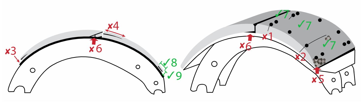
b) brake shoe lining condition (service brakes) Note: Cracks in the surface of the lining, surface erosion and minor spalling of the contact face of the lining are normal. Also inspect lining for damage caused by “”. This includes lining material cracking, lifting or separating from backing metal, due to rust build-up. When the lining protrudes outside of the brake drum, drum removal is necessary to obtain lining thickness. | b) a crack extending partially through, or completely through the lining from the friction surface to the metal backing, passing from any rivet hole to the edge a crack in the edge of the lining that is wider than 1 mm or longer than 38 mm a piece of the lining is broken off exposing a rivet or bolt lining is distorted or separating from shoe, (e.g.: an object 1 mm thick can be inserted more than 10 mm between the lining and the backing metal) lining is contaminated by oil or grease (Also see section 9 item 4 of this Vehicle Inspection Manual for wheel seal leaks) lining protrudes outside of drum more than 3 mm lining or any lining fastener is shim is used between lining and shoe shoe or lining is installed incorrectly (such as primary and secondary shoes reversed) | 2, 3, 4, 5 |
| ||
c) brake shoe lining thickness Additional Inspection Procedure(s): | c) bonded or riveted continuous strip brake shoe lining thickness is less than 5 mm at any point bolted or riveted block type brake shoe lining thickness is less than 8 mm at any point 8 mm = 0.3 (5/16) in., 5 mm = 0.2 (3/16) in. Note: For minimum allowable thickness, lining measurements are taken at the thinnest point of the lining. For the purposes of recording lining thickness on the inspection report, lining thickness measurements are taken at the edge of the lining, near the center of the brake shoe. The measurement must be taken of the thinner brake shoe lining, when there is a difference in thickness. | 2, 3, 4, 5 |
d) brake drum condition Note: Heat checks and some surface cracks on the friction surface are normal. A heat check has a width less than 0.5 mm and a depth less than 0.5 mm. A surface crack is at least 0.5 mm wide and 0.5 mm deep. Any surface crack, groove or worn area that is deeper than the drum wear limit is a structural weakness. | d) surface crack longer than 75% of the width of the friction surface surface crack within 25 mm of the open edge surface crack, groove or worn area that is a structural weakness external crack friction surface is , or is hardened and blackened due to overheating (“martensite”) friction surface is contaminated by grease or oil (Also see section 9 item 4 of this Vehicle Inspection Manual for wheel seal leaks) | 2, 3, 4, 5 |
e) brake drum diameter (wear) Additional Inspection Procedure(s): Note: Drum diameter measurements must be taken using a suitable tool and with the level of accuracy defined by the measurement tolerance. | e) measured drum diameter:
has one or more grooves worn so that measurement in groove exceeds wear limit:
| 2, 3, 4, 5 |
f) wheel seal | f) of bearing lubricant | 2, 3, 4, 5 |
g) return spring | g) , broken or stretched (fails to hold both rollers against cam) | 2, 3, 4, 5 |
h) spider | h) bent, broken, , welded or repaired in a way that does not meet mounting bolt | 2, 3, 4, 5 |
i. any part is binding, broken, , seized, or mounted incorrectly
ii. a brake drum is in a condition where an imminent failure appears likely
iii. a brake is
iv. bonded or riveted continuous strip brake shoe lining thickness is less than 5 mm at centre of shoe
v. bolted or riveted block type brake shoe lining thickness is less than 7 mm, at centre of shoe
vi. brake shoe lining is less than 1 mm at any point
vii. a piece of the lining is broken off exposing a rivet or bolt
viii. a crack in the edge of the lining wider than 1 mm
ix. a crack in the edge of the lining longer than 38 mm
x. broken or return spring, anchor pin, or spider
xi. brake lining or drum friction surface is contaminated by grease or oil
xii. mismatch of brake chamber size
Note: Also see section 9 item 4 of this Vehicle Inspection Manual for wheel seal leaks
5 mm = 0.2 (3/16) in., 7 mm = 0.25 in. (1/4) in.
16. S-Cam Drum Brake System
Additional Inspection Procedure(s):
Measure and record the applied push rod stroke of each brake with 620 to 690 kPa (90 to 100 psi) in the air tanks, the spring brakes released, the engine shut off and service brakes fully applied. Push-rod measurements must be recorded on the inspection form prior to commencing camshaft rotation. See “brake adjustment” below.
Back off the slack adjuster until movement is noticed in the brake chamber push rod. The roller will now be in the bottom position of the S-cam. Brake S-cam bushings should be inspected at this time. Mark the slack adjuster in relation to the camshaft with chalk. (Adjust the brakes to lock the wheel.) Ensure the brakes properly adjusted after test. This test is not required when drums are removed from the vehicle.
Dust shields must be removed.
Note: Also applies to T-Cam brake system.
Item and method of inspection | Reject if | Inspection Class |
|---|---|---|
a) camshaft condition Additional Inspection Procedure(s): | a) camshaft is bent, twisted, repaired by welding, incorrectly installed or incorrect type movement of camshaft in bushing exceeds 2.0 mm or difference between marks is more than 120° or 1/3 of camshaft travel overcammed, , binds, sticking Note: In the event brake drums are suspected of being oversized, the wheels and drums must be removed and the drums measured, or the drums may be measured by an alternate type of measuring device, using another method, provided the device/method measures drum wear accurately. All measurements must be recorded on the inspection form. | 2, 3, 4, 5 |
b) camshaft mounting | b) mounting bracket broken or | 2, 3, 4, 5 |
c) pushrod, clevis yoke, clevis pin and locking device Note: Brake pushrod stroke indicators are required by 121 on vehicles manufactured on and after May 31, 1996. These indicators normally consist of markings on the brake chamber pushrod, but can also be mounted on, or adjacent to, the brake linkage. They must be capable of showing an over-stroke condition. | c) worn, bent, binding, broken, cracked, , welded or repaired in a way that does not meet clevis yoke lock nut is linkage is misaligned to slack adjuster or brake chamber does not form correct angle with slack adjuster when brakes are applied (see note below) Note: the correct angle is an 80 - 100 degree angle (where applicable), or as close as practicable. Not all manufacturers obtain this angle. Refer to specifications. brake stroke indicator is incorrect pushrod length Note: Verify the pushrods are cut to proper length and meet chamber type specifications. | 2, 3, 4, 5 |
d) brake adjuster Note: Self-adjusting brake adjusters are required by 121 on vehicles manufactured on and after May 31, 1996. They cannot be replaced with manual brake adjusters. | d) not equipped with self-adjuster as required adjuster is or improperly installed improper type or size brake adjuster is used any part is bent, broken or the self-locking sleeve on a manual slack adjuster is seized or fails to lock | 2, 3, 4, 5 |
e) slack adjuster effective length | e) the distance from the center of a camshaft to the center of the clevis pin is not the same on all brakes of an axle | 2, 3, 4, 5 |
f) brake shoe roller | f) flat spots, , wrong size | 2, 3, 4, 5 |
g) brake shoe anchor pin | g) , wear allows the lining to protrude beyond outside edge of brake drum | 2, 3, 4, 5 |
h) brake stroke Additional Inspection Procedure(s): | h) stroke is at or beyond the limit of the brake chamber as shown in the “Brake Stroke Limits For Clamp-Type Brake Chambers” subsection below difference between stroke measurements is greater than 6 mm on an axle Note: The stroke measurements of all brakes are to be recorded on the inspection report. | 2, 3, 4, 5 |
i. camshaft is incorrectly installed, incorrect type, or mounting is
ii. improper type or size camshaft roller is used
iii. improper type or size brake adjuster is used on a steer axle
iv. broken or cam roller, camshaft, pushrod, yoke, clevis pin, clevis pin retainer, (e.g., cotter pin)
v. stroke of any brake is beyond the limit of the brake chamber as shown in the chart below
vi. camshaft travel exceeds 120 degrees
vii. camshaft is
Brake Stroke Limits For Clamp-Type Brake Chambers
Chamber Type (Size) | Stroke Limit (mm) | Stroke Limit (in.) |
|---|---|---|
6 | 32 | 1 - 1/4 |
9 | 35 | 1 - 3/8 |
12 | 35 | 1 - 3/8 |
12L | 44 | 1 - 3/4 |
16 | 44 | 1 - 3/4 |
16L | 51 | 2 |
20 | 44 | 1 - 3/4 |
20L | 51 | 2 |
24 | 44 | 1 - 3/4 |
24L | 51 | 2 |
24XL | 64 | 2 - 1/2 |
30 | 51 | 2 |
30L | 64 | 2 - 1/2 |
30DD3 | 57 | 2 - 1/4 |
36 | 57 | 2 - 1/2 |
17. Brake Shoe Travel (Wedge Brakes)
Item and method of inspection | Reject if | Inspection Class |
|---|---|---|
a) brake shoe movement Additional Inspection Procedure(s): | a) brakes fail to operate, shoes do not move or shoe movement exceeds 2 mm | 2, 3, 4, 5 |
i. shoe movement is greater than 2 mm
ii. any wedge brake is
18. Disc Brake System Components
Additional Inspection Procedure(s): When an inspection reveals evidence of a defect or abnormal condition, wheel disassembly is mandatory.
Item and method of inspection | Reject if | Inspection Class |
|---|---|---|
a) brake operation | a) a required brake is a brake is | 2, 3, 4, 5 |
b) disc (rotor) condition Note: Heat checks and some surface cracks on the friction surface are normal. A heat check has a width less than 0.5 mm and a depth less than 1 mm. A surface cracks is at least 0.5 mm wide and 1 mm deep. Lateral run-out and parallelism only need to | b) section is broken off or crack extends from the friction surface through to the cooling vent any surface crack is longer than 75% of the radial width, within the friction surface any surface crack extends to an outer edge groove or pitted area in rotor that reduces rotor thickness below minimum allowable value contact pattern of the pad on solid rotor material, (i.e.: not rusted) is less than 75% of the radial width, around the entire rotor, on one side lateral run-out or out-of-parallelism exceeds 0.3 mm friction surface of the rotor is contaminated by grease or oil (also see section 9 item 4 of this Vehicle Inspection Manual for wheel seal leaks) disc not vented properly hot spots are present that cannot be removed by machining | 2, 3, 4, 5 |
c) disc (rotor) thickness Additional Inspection Procedure(s): | c) thickness at any point across the friction surface is:
two or more grooves worn beyond 2.3 mm (3/32 in.) (0.090 in.) lateral run-out exceeds 0.25 mm (0.01 in.) | 2, 3, 4, 5 |
d) caliper | d) any part is binding, broken, seized, , or mounted incorrectly or does not meet the slide pin/slider or pad slider is binding, , seized, ly mounted, or does not meet the caliper movement within the anchor plate exceeds specification, guide is welded or repaired in a way that does not meet pad retainer is bent, , or boot or bellows is cracked or deteriorated, , or | 2, 3, 4, 5 |
e) anchor plate | e) or bolt is | 2, 3, 4, 5 |
f) pad condition | f) broken, cracked, , or friction material is contaminated by oil or grease (Also see section 9 item 4 of this Vehicle Inspection Manual for wheel seal leaks) rivet on pad, pad on bonded lining, pad is , or pad is installed incorrectly | 2, 3, 4, 5 |
g) pad (friction material) thickness Additional Inspection Procedure(s): Note: Pad (friction material) thickness can be determined by measuring the friction material itself or by measuring the combined thickness of the friction material and pad backing plate, then deducting the thickness of the backing plate. Always record the thickness of the friction material only. | g) measured friction material thickness is:
difference between inboard and outboard friction material thickness is:
3 mm = 0.12 (1/8) in., 5 mm = 0.20 (3/16) in. | 2, 3, 4, 5 |
h) clearance between pads and rotor (caliper adjustment) | h) does not meet specifications | 2, 3, 4, 5 |
i. any part is binding, broken, , seized, or mounted incorrectly
ii. a rotor (disc) friction surface shows metal to metal contact with brake pad or severe rusting
iii. a rotor (disc) has a crack that extends to the hub or through to the vented section
iv. caliper movement within the anchor plate exceeds 3 mm
v. any brake component is in a condition where an imminent failure appears likely
vi. a brake is
vii. brake pad friction material worn to less than 2 mm or a portion of the friction material is
viii. or brake chamber or caliper mounting bolt
ix. friction material of the pad or friction surface of the rotor is contaminated by grease or oil x. mismatched chamber size
Note: Also see section 9 item 4 of this Vehicle Inspection Manual for wheel seal leaks
2 mm = 0.08 in., 3 mm = 0.12 (1/8) in.
19. Anti-Lock Brake System (ABS) on Truck and Bus
Note: Every towing vehicle with air brakes manufactured on or after March 1, 2001 must be capable of PLC communication with any towed trailer.
Every vehicle equipped with that was not mandatory for the vehicle when it was manufactured must have in good working order.
Item and method of inspection | Reject if | Inspection Class |
|---|---|---|
a) indicator lamp Additional Inspection Procedure(s): | a) or fails to turn on during bulb-check cycle when ignition is turned on indicates the presence of an active malfunction by staying on after the bulb-check cycle any visual evidence that the system has been tampered with or defeated | 2, 4, 5 |
b) wiring Additional Inspection Procedure(s): Note: Also see requirement for towing vehicle to supply | b) mounting, , or connector corroded conductor is exposed due to damage, improper repair or other condition of wire connection or repair does not meet | 2, 4, 5 |
c) electronic control unit (ECU) | c) , mounting, connectors corroded | 2, 4, 5 |
d) relay/modulating valve | d) , leaking, mounting to ECU, abnormal corrosion | 2, 4, 5 |
e) wheel speed sensor Note: Different configurations of sensors and modulators are permitted by . Be sure to confirm the configuration of the before rejecting a vehicle due to wheel | e) , mounting, , connectors corroded | 2, 4, 5 |
f) PLC communication Additional Inspection Procedure(s): | f) PLC signal from trailer or test device fails to activate the trailer indicator lamp on instrument panel | 2, 4, 5 |
g) presence | g) on vehicles manufactured on or after April 1, 2000. | 2, 4, 5 |
i. any malfunction of the system that prevents normal brake operation
20. Anti-Lock Brake System (ABS) on Trailer
Note: ABS is not required by 121 for: trailers with width greater than 2.6 m, any vehicle equipped with an axle that has a GAWR greater than 13,154 kg; greater than 54,432 kg – “heavy hauler trailer”; and any load divider dolly.
Every vehicle equipped with that was not mandatory for the vehicle when it was manufactured including those listed in the exceptions below must have in good working order.
Item and method of inspection | Reject if | Inspection Class |
|---|---|---|
a) indicator lamp (trailer-mounted) Additional Inspection Procedure(s): Test Method #1. Connect to towing vehicle manufactured after March 1, 2001 that has been verified to have a properly functioning . Test Method #2. Using suitable test equipment, confirm that trailer control module sends required signal to operate dash mounted lamp in towing vehicle. | a) , not amber in colour is not marked “” on the lamp itself, or not marked “” within 150 mm of the lamp is not between 150 mm and 600 mm away from the left rear red side marker lamp fails to turn on during bulb-check cycle when power is supplied to auxiliary circuit (center pin, blue wire) indicates the presence of an active malfunction by staying on after the bulb-check cycle any visual evidence that the system has been tampered with or defeated | 3 |
b) wiring Additional Inspection Procedure(s): | b) mounting, , or connector corroded conductor is exposed due to damage, improper repair or other condition of wire connection or repair does not meet | 3 |
c) electronic control unit (ECU) | c) , mounting, connectors corroded | 3 |
d) relay/ modulating valve | d) , leaking, mounting to ECU, abnormal corrosion | 3 |
e) wheel speed sensor Note: Different configurations of sensors and modulators are permitted by . Be sure to confirm the configuration of the before rejecting a vehicle due to wheel | e) , mounting, , connectors corroded | 3 |
f) PLC signal to towing vehicle Note: Power Line Carrier (PLC) communication is | f) PLC signal is not transmitted by trailer Note: When using Test Method 1 for the indicator lamp (trailer-mounted) above, PLC communication from the trailer is verified when the dash-mounted trailer lamp in the towing vehicle turns on during bulb- check, and then turns off or stays on, to show the presence of a malfunction in conjunction with the trailer-mounted indicator lamp. A malfunction may be described as a Fault, Diagnostic Fault Code, or Diagnostic Trouble Code. | 3 |
g) presence | g) on vehicles manufactured on or after April 1, 2000 | 3 |
i. any malfunction of the system that prevents normal brake operation
21. Stability Control System on Truck or Bus
Additional Inspection Procedure(s): Check the ECU for indication of any fault or
malfunction.
Item and method of inspection | Reject if | Inspection Class |
|---|---|---|
a) indicator lamp Additional Inspection Procedure(s): | a) fails to illuminate or lamp remains illuminated fault or malfunction is indicated Note: Each of the conditions above are to be recorded on the inspection report, however a vehicle is not rejected for this condition alone. | 2, 4, 5 |
b) operation | b) any visual evidence that the system has been tampered with or defeated Note: The condition above is to be recorded on the inspection report, however a vehicle is not rejected for this condition alone. | 2, 4, 5 |
22. Stability Control System (Electronic Stability Control [ESC] or Roll Stability System [RSS]) on Trailer
Additional Inspection Procedure(s): Check the ECU for indication of any fault or malfunction in conjunction with inspection of the as described in item 20 above.
Item and method of inspection | Reject if | Inspection Class |
|---|---|---|
a) operation | a) there is evidence that the system has been tampered with or defeated the system has an active fault (light or indicator) Note: Each of the conditions above are to be recorded on the inspection report, however a vehicle is not rejected for this condition alone. | 3 |