Section 4 - Steering
All inspection procedures are visual unless additional inspection procedures are indicated or where applied force is necessary to verify tightness and/or component security. The definitions can be found in the “Definitions and Acronyms” section.
Right Hand Drive Vehicles additional inspection requirements (see Appendix D).
1. Steering Control and Linkage
Additional Inspection Procedure(s): Check the steering components listed below using tools and methods according to service instructions.
Item and method of inspection | Reject if | Inspection Class |
|---|---|---|
a) steering box or rack and pinion unit Additional Inspection Procedure(s): With vehicle on a level floor and with engine shut down, rock the steering wheel left and then right and observe movement in steering components. If movement is observed, grasp the tie rod and attempt to move it in the | a) or mounting, mounting bolt , , threads stripped any movement in mounting bushings housing broken, cracked, or of oil or fluid | 1, 2, 3, 4, 5, 6 |
b) bellow, clamp and boot | b) leaking, , , split or torn bulging, swollen or discoloured due to oil leak from internal end seal clamp , bent, welded or mounted | 1, 2, 3, 4, 5, 6 |
c) tie rod | c) bent, broken, cracked or welded, or repaired in a way that does not meet | 1, 2, 3, 4, 5, 6 |
d) tie rod end, drag link and ball and socket joint | d) bent, , or worn threads stripped or repaired a ball and socket joint is worn beyond manufacturer , welded, injected or repaired in a way that does not meet part is used that does not meet part is used that is not designed for use in automotive steering systems | 1, 2, 3, 4, 5, 6 |
e) pitman arm | e) bent, , or on spline repaired by welding | 1, 2, 3, 4, 5 |
f) idler arm | f) worn, , or repaired by welding | 1, 2, 3, 4, 5 |
g) ball-joint in upper or lower control arm Additional Inspection Procedure(s): For ball joints check as per original equipment methods. Check with dial indicator | g) in knuckle or control arm wear exceeds limit shown by wear indicator Note: If equipped with wear indicator and the collar of the grease fitting is flush with or below the bottom of the ball joint housing, the ball joint is worn and the item must be rejected. does not meet if wear indicator is not available does not meet if wear indicator and are not available or improper or retainer injected with repair material | 1, 2, 3, 4, 5, 6 |
h) cotter pin or similar retaining device | h) , or deficient part is used that does not meet | 1, 2, 3, 4, 5, 6 |
i) steering dampener | i) or of dampener fluid | 1, 2, 3, 4, 5, 6 |
j) steering column | j) mounting or mounting fastener or | 1, 2, 3, 4, 5 |
k) telescopic/tilt steering Additional Inspection Procedure(s): Check the operation of locking device(s). With unit locked, grasp the steering column and attempt to move it horizontally and vertically on its mounts. Note: Mounting solid rather than repairing is permitted. | k) movement exceeds specification, or when specification is not available, is greater than 6 mm | 1, 2, 3, 4, 5 |
l) steering shaft universal joint and yoke | l) binding, , seized, welded or repaired in a way that does not meet horizontal or vertical movement within the universal joint can be detected by hand clamp bolt or , or spline or stripped | 1, 2, 3, 4, 5, 6 |
m) steering column slip joint Additional Inspection Procedure(s): | m) rotational free play between splines exceeds 1 mm total side to side, or up and down movement exceeds 6 mm 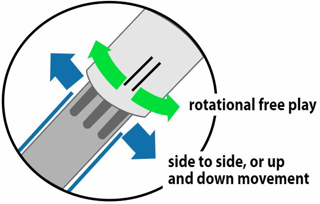 | 1, 2, 3, 4, 5 |
n) adjusting sleeve | n) bent, or welded or repaired in a way that does not meet tightening bolt is in a position that interferes with normal steering | 1, 2, 3, 4, 5, 6 |
o) remote (right hand) steering control | Note: Inspect as described in Section 5 - Instruments and Auxiliary Equipment of this Vehicle Inspection Manual | 1, 2, 4, 5 |
i. any crack, modification or other condition that interferes with free movement of any steering component, or repair that does not meet
ii. any positioning parts allow movement from normal position
Steering Box or Rack & Pinion Unit
iii. cracked, or mounting, mounting bolt or or has been repaired in way, (e.g.: welded) that does not meet
Steering Linkage
iv. any ball and socket joint has ness in line with the shank or neck of the ball greater than specification, or when specification is not available, greater than 3.0 mm
v. the socket of a ball and socket joint is injected with any repair material, or a ball and socket joint has been repaired in way, (e.g.: welded) that does not meet
vi. pitman arm is on steering gear output shaft spline or has been repaired in way, (e.g.: welded) that does not meet
vii. any nut is or
viii. clamp, clamp bolt or nut on tie rod, drag link, pitman arm, or steering arm
ix. any ness in any threaded joint
Steering Column and Related Parts
x. adjusting sleeve is or
xi. or mounting, mounting bolt or
xii. column fails to lock into position
xiii. a universal joint has been repaired in way, (e.g.: welded) that does not meet
xiv. any ness of the yoke-coupling at the steering gear input shaft
2. Power Steering System (Hydraulic and Electric)
Additional Inspection Procedure(s): Inspect the power steering components with the engine stopped. Then with engine running, turn wheels fully to the left and right and check system operation.
Item and method of inspection | Reject if | Inspection Class |
|---|---|---|
a) fluid | a) below indicated minimum level or fluid is contaminated | 1, 2, 4, 5, 6 |
b) belt | Note: Inspect drive belt according to Section 1. Power Train, Item 10. Engine or Accessory Drive Belt of this Vehicle Inspection Manual. | 1, 2, 4, 5, 6 |
c) hose | c) cracked, worn by or is in contact with moving parts distance to exhaust system component is less than 25 mm of power steering fluid | 1, 2, 4, 5, 6 |
d) pump | d) , mounting, or of power steering fluid | 1, 2, 4, 5, 6 |
e) cylinder or box | e) , mounting, , or of power steering fluid | 1, 2, 4, 5, 6 |
f) mounting bracket | f) broken, cracked or bolt or | 1, 2, 4, 5, 6 |
g) assist Additional Inspection Procedure(s): If equipped with hydraulic assisted brake booster apply brakes and turn steering wheel with engine running and check assist. | g) (i.e.: power-assist provided is noticeably reduced requiring more than normal steering effort to turn the wheels left or right) | 1, 2, 4, 5, 6 |
h) hose location | h) within 25 mm (1 in.) of exhaust system | 1, 2, 4, 5 |
i. power steering is
ii. any steering component is in a condition where imminent failure appears likely
iii. of power steering fluid
iv. auxiliary power assist cylinder is
3. Steering Operation (Active Steer Axle)
Note: An active steer axle is one that is directly controlled by the steering wheel. Check steering operation after inspecting steering control and linkage, and checking power steering as described above.
Item and method of inspection | Reject if | Inspection Class |
|---|---|---|
a) steering wheel | a) broken, , on spline or modified does not meet specifications Note: Steering wheels shall be of substantially the same size, shape and strength as the steering wheel supplied by the of the motor vehicle. (Section 19 of the Schedule to Division 7 of the MVAR) | 1, 2, 4, 5 |
b) rotation and travel Additional Inspection Procedure(s): | b) binds or jams during rotation number of rotations from center to full left does not equal the number of rotations from center to full right, +/- ½ turn | 1, 2, 4, 5 |
c) steering lash or free-play Additional Inspection Procedure(s): Measure lash or free-play beginning with wheels in straight-ahead position. Then turn steering wheel just until turning motion can be observed at the front wheels. Mark rim of steering wheel and turn the steering wheel in the opposite direction until motion can just be observed. Measure the distance of steering wheel rotation that does not cause turning of the wheels. | c1) inspection class 1: a total movement greater than shown in the following table is encountered at the steering wheel rim before the front wheels indicate movement.
c2) inspection classes 2, 4, 5: steering lash or free-play is greater than the distance shown below
| 1, 2, 4, 5 |
d) tire clearance | d) space between tire and frame, fender or other vehicle part is less than 25 mm at any point in turn | 1, 2, 4, 5 |
e) steering stop | e) improperly adjusted, bent or | 1, 2, 4, 5 |
i. steering binds or jams during rotation
ii. steering lash or free-play is greater than the distance shown below:
power steering system
steering wheel diameter of 500 mm & less: 87 mm
steering wheel diameter over 500 mm: 100 mmmanual steering system
steering wheel diameter of 500 mm & less: 140 mm
steering wheel diameter over 500 mm: 196 mm
iii. steering column and wheel
any bolts are or or any positioning parts allow movement from normal position.
any universal joints are welded.
steering wheel not secure.
iv. Ball and sockets
any linkage shows ness in alignment with the shank or neck of the ball in excess of 3.2 mm (1/8 in.).
nuts on tie rod ends, adjusting sleeve, pitman arm, drag link or steering arm.
4. Kingpin
Additional Inspection Procedure(s): Raise the axle to unload the kingpin (if equipped, apply brakes to eliminate wheel bearing ness). Turn the wheels through a full right and left turn.
Item and method of inspection | Reject if | Inspection Class |
|---|---|---|
a) lateral movement Additional Inspection Procedure(s): Use a dial gauge if necessary. | a) not within specification or when specification is not available:
| 1, 2, 4, 5 |
b) vertical movement Additional Inspection Procedure(s): Use a dial gauge if necessary. | b) not within specification or when specification is not available, greater than 2.5 mm | 1, 2, 4, 5 |
c) condition | c) seized, binding or jamming is detected while turning wheel | 1, 2, 4, 5 |
i. binding or jamming caused by the kingpin or thrust bearings
5. Self-Steer and Controlled-Steer Axle
Additional inspection procedure(s): Additional items may require inspection than those listed below. Refer to service instructions related to the particular axle - for items in addition to those listed below - that are required to be inspected as part of a periodic safety inspection.
Note: These are passive steer axles. A passive steer axle responds only to lateral force to turn wheels.
The suspension components on a self-steer or controlled steer axle must be inspected according to Section 2, items 1-4 of this Vehicle Inspection Manual. The steering components must be inspected according to items 1 and 4 above.
Item and method of inspection | Reject if | Inspection Class |
|---|---|---|
a) operation Additional Inspection Procedure(s): | a) binding or jamming is detected while turning wheels | 2, 3, 4, 5 |
b) clearance | b) there is less than 25 mm between the tire and frame, fender or other vehicle part | 2, 3, 4, 5 |
c) steering stop | c) or not adjusted properly | 2, 3, 4, 5 |
d) air pressure regulator | d) or | 2, 3, 4, 5 |
e) pressure gauge | e) inaccurate, or not equipped with legible instruction indicating the minimum centering force pressure requirement | 2, 3, 4, 5 |
f) operating instruction label | f) not equipped with legible instruction indicating safe operation (such as: stating the speed at which the axle locks) | 2, 3, 4, 5 |
i. cracked, or mounting, mounting bolt or , or has been repaired in way that does not meet
ii. or steering lock on a C-dolly
iii. steering locks in any position except centered
Note: Also see Hazardous Conditions for items 1 to 4 in this section above
6. Motorcycle Handlebar
Item and method of inspection | Reject if | Inspection Class |
|---|---|---|
a) tubing | a) not made of 0.060 steel tube or equivalent strength cracked, deformed, improperly aligned or flex excessively repaired by welding | 6 |
b) height | b) maximum height to which the handlebars extend higher than the top of the driver’s shoulders when the driver’s seat is occupied | 6 |
c) steering head | c) steering head bearing shows any perceptible movement or is outside specification, | 6 |
d) security | d) handlebars are , or in any other way unsafe | 6 |
i) handlebar(s) broken, or part or component(s)
7. Wheel Alignment
Additional Inspection Procedure(s):
A wheel alignment must be performed if there is visible evidence of misalignment.
For more information regarding steering alignment angles see Appendix C.
7.1. Front Wheels
Item and method of inspection | Reject if | Inspection Class |
|---|---|---|
a) caster | a) not within specifications | 1, 2, 3, 4, 5, 6 |
b) camber | b) not within specifications | 1, 2, 3, 4, 5, 6 |
c) toe | c) not within specifications | 1, 2, 3, 4, 5, 6 |
d) Steering Axis Inclination (SAI) | d) not within specifications or the difference between right and left exceeds 0.5° | 1, 2, 3, 4, 5, 6 |
e) included angle | e) not within specifications or the difference between right and left exceeds 0.5° | 1, 2, 3, 4, 5, 6 |
f) total toe | f) not within specifications | 1, 2, 3, 4, 5, 6 |
g) set back | g) not within specifications or the difference between right and left exceeds 0.5° | 1, 2, 3, 4, 5, 6 |
h) turning angle | h) not within specifications or the difference between right and left exceeds 5° | 1, 2, 3, 4, 5, 6 |
i) condition | i) the longitudinal wheel alignment of a two-wheel does not pass within 12.5 mm of the front wheel centre line when measured at a point directly below the front axle | 6 |
j) wheelbase | j) less than 1016 mm | 6 |
7.2. Rear Wheels
Item and method of inspection | Reject if | Inspection Class |
|---|---|---|
a) camber | a) not within specifications | 1, 2, 3, 4, 5 |
b) toe | b) not within specifications | 1, 2, 3, 4, 5 |
c) total toe | c) not within specifications | 1, 2, 3, 4, 5 |
d) set back | d) not within specifications or the difference between right and left exceeds 0.5° | 1, 2, 3, 4, 5 |
e) thrust angle | e) not within specifications or the difference between right and left exceeds 0.5° | 1, 2, 3, 4, 5 |