Section 3H - Hydraulic Brakes
- Hydraulic System Components
- Brake Pedal/Actuator
- Mechanical Components
- Vacuum Assist (Boost) System
- Hydraulic Assist (Boost) System
- Air Assist (Boost) System on Truck or Bus
- Air-Over-Hydraulic Brake System
- Surge Brake Controller on Trailer
- Vacuum System on Trailer
- Air-Boosted Trailer Brake System
- Electric Brake System on Trailer
- Brake System Indicator Lamps
- Drum Brake System Components
- Disc Brake System Components
- Parking Brake
- Spring-Applied Air-Released (SAAR) Parking Brake
- Spring-Applied Hydraulic-Released (SAHR) Parking Brake
- Anti-Lock Brake System (ABS)
- Stability Control System
All inspection procedures are visual unless additional inspection procedures are indicated or where applied force is necessary to verify tightness and/or component security. The definitions can be found in the
1. Hydraulic System Components
Item and method of inspection | Reject if | Inspection Class |
|---|---|---|
a) metal line and fittings Additional Inspection Procedure(s): Note: All connections between brake system Surface rust and corrosion is normal on metal lines and fittings, and is not cause for rejection. | heavy rust, corrosion or scaling, is present on any metal line or fitting that reduces or increases the thickness, or compromises the structural integrity of the material of brake fluid chafing, cracked, flattened or restricting section mounting causing line to shift out of its normal position repaired by welding or soldering repaired using material or method does not meet | 1, 2, 3, 4, 5, 6 |
b) flexible line/hose Additional Inspection Procedure(s): | b) bulged or swells under pressure, flattened, twisted, restricting section or mounting outer composite material is cracked or chafed exposing an inner layer as shown in Appendix B deficient product is used that does not meet of brake fluid | 1, 2, 3, 4, 5, 6 |
c) master cylinder Additional Inspection Procedure(s): | c) or mounting fluid is contaminated of brake fluid fluid level is below indicated minimum level filler cap is , or , vent holes are plugged, or gasket is or swollen | 1, 2, 3, 4, 5, 6 |
d) pressure differential switch (if equipped) | d) switch or electrical connection is , or of brake fluid inoperative | 1, 2, 3, 4, 5, 6 |
e) variable or proportioning system Additional Inspection Procedure(s): | e) link is , , or seized inoperative of brake fluid | 1, 2, 3, 4, 5, 6 |
f) auxiliary or work brake (line-lock device) Note: Line-lock devices block brake fluid from returning to the master cylinder as a means of holding a vehicle stationary. Improperly installed they can interfere with normal service brake operation. | f) any device is installed that interferes with normal service brake operation | 1, 2, 3, 4, 5, 6 |
g) service brake function | g) brake does not apply or release as intended service brake pedal travel exceeds 80% of the specified available pedal travel or the available pedal travel | 1, 2, 4, 5, 6 |
h) proportioning valve Additional Inspection Procedure(s): Test function by applying just sufficient pressure to brake pedal to just lock both front wheels against hand rotation, the rear wheels should also be locked. | h) rear wheels fail to lock | 1, 2, 4, 5 |
i. a brake hose or line swells under pressure
ii. in any part of the brake system
iii. brake pedal moves downward when brakes are held applied
iv. a brake hose is broken, crimped, restricted, or cracked exposing any inner layer
v. master cylinder fluid level is below indicated minimum level or less than ¼ full
vi. brake fluid is contaminated in a way that prevents normal brake operation
vii. service brakes do not apply or release as intended
viii. breakaway brakes inoperative or
2. Brake Pedal/Actuator
Item and method of inspection | Reject if | Inspection Class |
|---|---|---|
a) pedal | a) broken, cracked, , or welded or repaired in a way that does not meet | 1, 2, 4, 5 |
b) mount | b) cracked, deteriorated, or weakened by corrosion | 1, 2, 4, 5 |
c) anti-slip feature | c) ineffective, or | 1, 2, 4, 5, 6 |
d) hand and foot levers | d) less than 1/3 travel remains as reserve with brakes normally applied, or do not return when released, or not to | 6 |
e) accessibility | e) foot brake pedal is not accessible for adequate leverage, or does not have a foot rest for use during braking | 6 |
f) hydraulic brake leakage and pedal reserve test Additional Inspection Procedure(s): With engine running if power brakes, and without pumping or repeated brake pedal application, apply a moderate foot | f) pedal moves slowly in applied direction, any fluid leakage is observed in system pedal travel from its free height to its depressed height is more than 65% of possible total travel or does not meet specifications excessive pedal free play service brake pedal requires pumping to maintain pedal reserve Note: Vehicles equipped with an electrically driven hydraulic pump that functions in the event of a power steering failure can be checked by applying moderate pressure | 1, 2, 4, 5, 6 |
i. pedal is
ii. any fluid leakage is observed in the system
iii. service brake pedal requires pumping to maintain pedal reserve
iv. pedal free play exceeds 80% of total brake pedal travel
3. Mechanical Components
Item and method of inspection | Reject if | Inspection Class |
|---|---|---|
a) brake cam operating lever | a) angle between cam operating lever and actuating cable or rod exceeds 110 degrees in fully applied position; lever repositioned on shaft to compensate for wear; maximum wear indicator exceeded | 6 |
b) cable and adjusters | b) cable frayed with one broken strand; cable or cables routed so as to be restricted by other components; no means for locking brake adjusters | 6 |
c) clevis, pins, rods, couplings | c) any clevis pin, cotter pin, spring, rod clevis or coupling is , excessively worn, broken or defective | 6 |
d) sidecar brake (if equipped) | d) not activated by rear brake application, vehicle does not meet regulatory stopping distance | 6 |
i. brake components cannot be adjusted to provide braking
ii. cotter pins or locking devices from the bolts securing either end of the brake torque link (disc or drum, rear; drum, front).
4. Vacuum Assist (Boost) System
Item and method of inspection | Reject if | Inspection Class |
|---|---|---|
a) line, hose and clamp | a) broken, chafed, collapsed, cracked, leaking, or mounting, incorrect type, or does not meet the location requirements outlined in Section 1 - Power Train, Item 2h | 1, 2, 4, 5 |
b) check valve | b) incorrectly installed or inoperative, leaking or | 1, 2, 4, 5 |
c) tank | c) , structurally deteriorated from corrosion, or , leaking or | 2, 4, 5 |
d) operation Additional Inspection Procedure(s): | d) during stage 1 - vacuum reserve is insufficient to assist two full brake applications during stage 2 - downward movement of brake pedal is not felt when engine is started | 1, 2, 4, 5 |
e) warning device | e) not equipped with an audible or visual signal in the event of failure of air pressure or braking effectiveness | 1, 2, 4, 5 |
f) vacuum pump Additional Inspection Procedure(s): | f) vacuum pump does not operate within specifications, or when no specification is available, is unable to achieve and maintain 4.5 kPa of vacuum Note: High altitude can reduce achievable vacuum level. | 1, 2, 4, 5 |
i. a brake hose or line swells under pressure
ii. in any part of the brake system
iii. applied pedal travel exceeds 80% of total pedal travel
iv. power assist unit is inoperative
v. a check valve is inoperative or
vi. the brake pedal does not move downward when the engine is started with the brakes applied
5. Hydraulic Assist (Boost) System
Item and method of inspection | Reject if | Inspection Class |
|---|---|---|
a) engine-driven pump, reservoir and belt Additional Inspection Procedure(s): Inspect drive belt according to Section 1. Power Train, Item 10. Engine or Accessory Drive Belt. | a) of hydraulic boost fluid fluid level is below indicated minimum level, or if not indicated, more than 25 mm from top filler cap is , or | 1, 2, 4, 5 |
b) line and hose Additional Inspection Procedure(s): | b) of hydraulic boost fluid broken, chafed, collapsed, cracked, or mounting or incorrect type | 1, 2, 4, 5 |
c) operation Additional Inspection Procedure(s): | c) hydraulic assist (boost) is not available or system malfunctions system does not operate as described in service instructions warning or indicator lamp is activated, showing a system malfunction during test method 1 - system does not operate as described in service instructions or electric driven pump is during test method 2 - on a system with gas- accumulator back-up - pedal fails to sink down and then push back up again | 1, 2, 4, 5 |
i. a brake hose or line swells under pressure
ii. in any part of the brake system
iii. applied pedal travel exceeds 80% of total pedal travel
iv. power assist unit is inoperative
v. a check valve is inoperative or
vi. the brake pedal does not move downward when the engine is started with the brakes applied
6. Air Assist (Boost) System on Truck or Bus
Item and method of inspection | Reject if | Inspection Class |
|---|---|---|
a) operation Additional Inspection Procedure(s): When no service instructions are available, check as follows: Stop engine and deplete pressure reserve. Then apply moderate force on the brake pedal and start the engine. | a) system does not operate as described in service instructions downward movement of brake pedal is not felt when engine is started | 2, 4, 5 |
i. a brake hose or line swells under pressure
ii. in any part of the brake system
iii. applied pedal travel exceeds 80% of total pedal travel
iv. power assist unit is inoperative
v. a check valve is inoperative or
vi. the brake pedal does not move downward when the engine is started with the brakes applied
7. Air-Over-Hydraulic Brake System
Note: An Air-Over-Hydraulic Brake System is a brake system that uses compressed air to transmit force from the driver control to a hydraulic brake fluid system that actuates the service brakes. The brake pedal is connected to an air valve that delivers air pressure to hydraulic pressure converters. The air system of an air-over-hydraulic brake system must comply with 121.
Item and method of inspection | Reject if | Inspection Class |
|---|---|---|
a) operation Additional Inspection Procedure(s): Inspect system operation according to service instructions. | a) system does not operate as described in service instructions a vehicle manufactured after 1975 does not have a dual-circuit air system and two independent air-to- hydraulic pressure converters any system defect or malfunction is detected | 2, 3, 4, 5 |
i. a brake hose or line swells under pressure
ii. in any part of the brake system
iii. applied pedal travel exceeds 80% of total pedal travel
iv. power assist unit is inoperative
v. a check valve is inoperative or
vi. the brake pedal does not move downward when the engine is started with the brakes applied
8. Surge Brake Controller on Trailer
Item and method of inspection | Reject if | Inspection Class |
|---|---|---|
a) controller operation Additional Inspection Procedure(s): | a) controller is or defective controller is seized, or fails to operate brakes when actuated manually backing/towing function fails to operate as intended | 3 |
b) brake fluid reservoir | b) mounting or of brake fluid brake fluid level is below ‘fill’ or ‘min.’ mark or less than 75% of capacity when reservoir is not marked reservoir filler cap , or | 3 |
c) break-away device Additional Inspection Procedure(s): | c) , , inoperative, improperly installed | 3 |
i. brakes are inoperative or fail to operate as intended
ii. required break-away device is improperly installed, inoperative or
9. Vacuum System on Trailer
Additional Inspection Procedure(s): When inspecting a trailer that uses vacuum to actuate or boost braking, inspect the system according to the service instructions.
Item and method of inspection | Reject if | Inspection Class |
|---|---|---|
a) condition and operation | a) or fails to operate as intended | 3 |
i. brakes are inoperative or fail to operate as intended
10. Air-Boosted Trailer Brake System
Additional Inspection Procedure(s): When inspecting a trailer that uses an air-boosted brake system, inspect the system according to the service instructions.
Item and method of inspection | Reject if | Inspection Class |
|---|---|---|
a) condition and operation | a) or fails to operate as intended | 3 |
i. brakes are inoperative or fail to operate as intended
11. Electric Brake System on Trailer
Additional Inspection Procedure(s): Wheels and drums must be disassembled on all electric brake systems.
Note: Inspect the wheel-end (drum or disc) brake system components on a trailer with electric brakes, according to the relevant requirements for drum or disc brake system as outlined in subsections 12 and 13 of this section.
Item and method of inspection | Reject if | Inspection Class |
|---|---|---|
a) wheel magnet and actuator Additional Inspection Procedure(s): | a) any part is broken, , , or magnet is inoperative or seized | 3 |
b) wiring | b) shorted, insulation is cracked or peeled improperly spliced or connected not secured at least every 1800 mm | 3 |
c) break-away device Additional Inspection Procedure(s): | c) see Item 8c in this section | 3 |
d) battery and controller Additional Inspection Procedure(s): | d) or fails to operate as intended | 3 |
i. brakes are inoperative or fail to operate as intended
ii. required break-away device is inoperative or
12. Brake System Indicator Lamps
Item and method of inspection | Reject if | Inspection Class |
|---|---|---|
a) operation Additional Inspection Procedure(s): Check operation of brake indicator lamps according to service instructions. When no service instructions are available, begin with engine stopped, then turn ignition on. Lamps must turn on when ignition is first turned on. Lamps may go out after 2 – 3 seconds or may stay on until the engine is started. | a) , not either red or amber in colour does not operate according to service instructions indicates a brake system malfunction or defect Note: Some indicator lamps may stay on, after a repair or system malfunction, until vehicle speed reaches 8 – 16 km/h. | 1, 2, 4, 5 |
i. any brake indicator is inoperative or fails to operate as intended
ii. an active brake failure is indicated
13. Drum Brake System Components
Additional Inspection Procedure(s): When an inspection reveals evidence of a defect or abnormal condition, drum disassembly is mandatory.
Note: Wheel removal does not apply to new vehicles where is supplied by Canadian or US .
13.1 Vehicles with a of 4536kg or less
Note: Bearing re-pack not part of the inspection. Pull all wheels and brake drums. Inspect linings and drums. Re-install wheel and drum assembly. Install new cotter pin. Record measurements on inspection forms.
Item and method of inspection | Reject if | Inspection Class |
|---|---|---|
a) brake operation | a) a required brake is a brake is inoperative | 1, 2, 3, 4, 5, 6 |
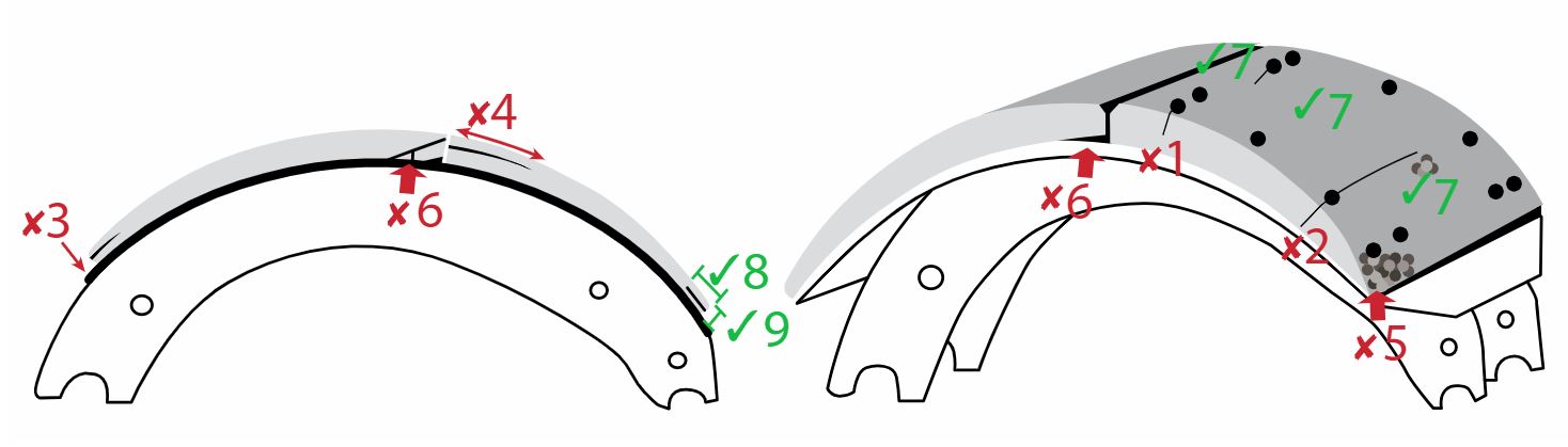
b) brake shoe lining condition (service brakes): Note: Cracks in the surface of the lining, surface erosion and minor spalling of the contact face of the lining are normal. Also inspect lining for damage caused by “”. This includes lining material cracking, lifting or separating from backing metal, due to rust build- up. | b) broken, cracked, , , contaminated lining is distorted or separating from shoe shoe or lining is installed incorrectly (such as primary and secondary shoes reversed) | 1, 2, 3, 4, 5, 6 |
c) brake shoe lining thickness Additional Inspection Procedure(s): For the purposes of recording lining thickness on the inspection report, lining thickness measurements are taken at the edge of the lining, near the centre of the brake shoe. The measurement must be taken of the thinner brake shoe lining, when there is a difference in thickness. | c) lining: Bonded Lining worn to 1 mm or less at the thinnest point Riveted Lining worn to 1.6 mm or less above rivet head, or to minimum as indicated by component over 1.6 mm | 1, 2, 3, 4, 5, 6 |
d) brake drum condition | d) cracks extend to the open edge of the drum any external cracks are present surface crack, groove or worn area that is a structural weakness Note: Any surface crack, groove or worn area that is deeper than the drum wear limit is a structural weakness. hot spots are present in more than one location that cannot be removed by machining within drum limits discolouration of metal in drum resulting in heat cracks that cannot be machined out within drum limits friction surface is uneven, chunk broken out of drum friction surface is , or is hardened and blackened due to overheating (“martensite”) friction surface is contaminated by grease or oil (Also see section 9 item 4 for wheel seal leaks) | 1, 2, 3, 4, 5, 6 |
e) brake drum diameter (wear) Additional Inspection Procedure(s): Measure inside diameter of drum at two locations at centre of drum face and approximately 90 degrees apart. Note: Drum diameter measurements must be taken using a suitable tool. | e) drum has more than one groove worn so that measurement in groove exceeds wear limits:
measured drum diameter exceeds limit indicated on the brake drum, or if limit is not available:
2.3 mm = 0.09 in. | 1, 2, 3, 4, 5, 6 |
f) self-adjuster mechanism | f) , incorrect thread direction, , or seized cable and linkage , , broken, cable frayed | 1, 2, 3, 4, 5, 6 |
g) anchor pin and return spring | g) , bent, broken, or spring stretched, bent or no spring tension | 1, 2, 3, 4, 5, 6 |
h) backing plate | h) bent, or shoe contact area is grooved or worn in a manner that restricts free movement of shoes | 1, 2, 3, 4, 5, 6 |
i) wheel cylinder | i) , or seized, or mounting of brake fluid dust seal is cracked, , deteriorated, , or split | 1, 2, 3, 4, 5, 6 |
j) wheel seal | j) of bearing lubricant | 1, 2, 3, 4, 5, 6 |
i. brake drum in a condition which could indicate failure is imminent
ii. brake
iii. metal to metal
iv. contaminated lining
v. lining to point of separation
13.2 Vehicles with a of more than 4536kg
Item and method of inspection | Reject if | Inspection Class |
|---|---|---|
a) brake operation | a) a required brake is a brake is | 1, 2, 3, 4, 5 |
b) brake shoe lining condition (service brakes): Note: Cracks in the surface of the lining, surface erosion and minor spalling of the contact face of the lining are normal. Also inspect lining for damage caused by “”. This includes lining material cracking, lifting or separating from backing metal, due to rust build-up. | b) a crack extending partially through, or completely through the lining from the friction surface to the metal backing, passing from any rivet hole to the edge a crack in the edge of the lining that is wider than 1 mm or longer than 38 mm a piece of the lining is broken off exposing a rivet lining is distorted or separating from shoe, (e.g.: an object 1 mm thick can be inserted more than 10 mm between the lining and the backing metal) lining is contaminated by brake fluid, oil or grease (Also see section 9 item 4 for wheel seal leaks) lining protrudes outside of drum more than 3 mm lining or any lining fastener is - shim is used between lining and shoe shoe or lining is installed incorrectly (such as primary and secondary shoes reversed) | 1, 2, 3, 4, 5 |
| ||
c) brake shoe lining thickness Additional Inspection Procedure(s): For the purposes of recording lining thickness on the inspection report, lining thickness measurements are taken at the edge of the lining, near the centre of the brake shoe. The measurement must be taken of the thinner brake shoe lining, when there is a difference in thickness. | c) bonded brake shoe lining thickness is less than 2 mm at any point bolted or riveted brake shoe lining thickness is less than 3 mm at any point 2 mm = 0.08 in. | 1, 2, 3, 4, 5 |
d) brake drum condition Note: Heat checks and some surface cracks on the friction surface are normal. A heat check has a width less than 0.5 mm and a depth less than 0.5 mm. A surface crack is at least 0.5 mm wide and 0.5 mm deep. Any surface crack, groove or worn area that is deeper than the drum wear limit is a structural weakness. | d) surface crack longer than 75% of the width of the friction surface surface crack within 25 mm of the open edge surface crack, groove or worn area that is a structural weakness external crack friction surface is , or is hardened and blackened due to overheating (“martensite”) friction surface is contaminated by grease or oil (Also see section 9 item 4 for wheel seal leaks) | 1, 2, 3, 4, 5 |
e) brake drum diameter (wear) Additional Inspection Procedure(s): Note: Drum diameter measurements must be taken using a suitable tool and with the level of accuracy defined by the measurement tolerance. | e) measured drum diameter exceeds limit indicated on the brake drum, or if limit is not available:
2.3 mm = 0.09 in. | 1, 2, 3, 4, 5 |
f) self-adjuster mechanism | f) , incorrect thread direction, , or seized | 1, 2, 3, 4, 5 |
g) anchor pin and return spring | g) , bent, broken, or spring stretched | 1, 2, 3, 4, 5 |
h) backing plate | h) bent, or shoe contact area is grooved or worn in a manner that restricts free movement of shoes | 1, 2, 3, 4, 5 |
i) axle and spindle | i) cracked | 1, 2, 3, 4, 5 |
j) wheel cylinder | j) , or seized, or mounting of brake fluid dust seal is cracked, , deteriorated, , or split | 1, 2, 3, 4, 5 |
k) wheel seal | k) level 2 leak of bearing lubricant | 1, 2, 3, 4, 5 |
i. any part is binding, broken, , seized, or mounted incorrectly
ii. a brake drum is in a condition where an imminent failure appears likely
iii. of brake fluid at wheel cylinder
iv. a brake is
v. brake lining thickness is less than 2 mm
vi. a piece of the lining is broken off exposing a rivet or bolt
vii. a crack in the edge of the lining wider than 1 mm
viii. a crack in the edge of the lining longer than 38 mm
ix. broken or return spring, anchor pin, or spider
x. brake lining or brake drum friction surface is contaminated by brake fluid, grease or oil
Note: Also see section 9 item 4 for wheel seal leaks
14. Disc Brake System Components
Additional Inspection Procedure(s): Pull all wheels. Using a micrometer or dial indicator, inspect and record measurements.
Note: Wheel removal does not apply to new vehicles where is supplied by Canadian or US .
14.1. Vehicles with a of 4536kg or less
Item and method of inspection | Reject if | Inspection Class |
|---|---|---|
a) brake operation | a) a required brake is a brake is | 1, 2, 3, 4, 5, 6 |
b) disc (rotor) condition | b) broken, pitted or any surface crack extends to an outer edge crack extends from the friction surface through to the cooling vent any surface crack is longer than 75% of the radial width, within the friction surface groove or pitted area in rotor that reduces rotor thickness below minimum allowable value contact pattern of the pad on solid rotor material (i.e.: not rusted) is less than 75% of the radial width, around the entire rotor, on one side hot spots are present that cannot be removed by machining disc not vented properly friction surface of the rotor is contaminated by brake fluid, grease or oil (also see section 9 item 4 for wheel seal leaks) | 1, 2, 3, 4, 5, 6 |
c) disc (rotor) thickness Additional Inspection Procedure(s): | c) one groove worn beyond 2.3 mm (3/32 in.) lateral run-out exceeds 0.125 mm on disc 380 mm (15 in.) diameter or less lateral run-out exceeds 0.25 mm on discs greater than 380 mm (15 in.) diameter thickness at any point across the friction surface is less than the minimum indicated on the brake rotor, or Note: Original thickness may not be decreased by any combination of wear and machining below minimum thickness. | 1, 2, 3, 4, 5, 6 |
d) caliper | d) any part is binding, , broken, , seized, mounted incorrectly or does not meet the caliper movement within the anchor plate exceeds specification, guide is welded or repaired in a way that does not meet any leak of brake fluid pad retainer is bent, , or boot or bellows is cracked or deteriorated, , or bleeder caliper assembly worn beyond specifications | 1, 2, 3, 4, 5, 6 |
e) anchor plate | e) or bolt is | 1, 2, 3, 4, 5, 6 |
f) pad condition | f) broken, cracked, , , or friction material is contaminated by brake fluid, oil or grease (also see section 9 item 4 for wheel seal leaks) friction material on pad, pad is , or pad is installed incorrectly rivets | 1, 2, 3, 4, 5, 6 |
g) pad (friction material) thickness | g) pad (measured friction material) thickness is less than specification, or if limit is not available:
| 1, 2, 3, 4, 5, 6 |
i. any disc is cracked to the hub or failure appears imminent
ii. brake
iii. metal to metal
14.2. Vehicles with a of more than 4536kg
Item and method of inspection | Reject if | Inspection Class |
|---|---|---|
a) brake operation | a) a required brake is a brake is | 2, 3, 4, 5 |
b) disc (rotor) condition Note: Heat checks and some surface cracks on the friction surface are normal. A heat check has a width less than 0.5 mm and a depth less than 1 mm. A surface crack is at least 0.5 mm wide and 1 mm deep. Lateral run-out and parallelism only need to | b) section is broken off or crack extends from the friction surface through to the cooling vent any surface crack is longer than 75% of the radial width, within the friction surface any surface crack extends to an outer edge groove or pitted area in rotor that reduces rotor thickness below minimum allowable value contact pattern of the pad on solid rotor material (i.e.: not rusted) is less than 75% of the radial width, around the entire rotor, on one side lateral run-out or out-of-parallelism exceeds 0.3 mm friction surface of the rotor is contaminated by brake fluid, grease or oil (also see section 9 item 4 for wheel seal leaks) 0.3 mm = 0.01 in. disc not vented properly hot spots are present that cannot be removed by machining | 2, 3, 4, 5 |
c) disc (rotor) thickness Additional Inspection Procedure(s): | c) thickness at any point across the friction surface is less than the minimum indicated on the brake rotor, or if limit is not available:
two grooves worn beyond maximum 2.3 mm lateral run out exceeds 0.128 mm (0.005 in.) on lateral run out exceeds 0.25 mm (0.01 in.) on discs | 2, 3, 4, 5 |
d) caliper | d) any part is binding, broken, , seized or mounted incorrectly or does not meet the slide pin/slider or pad slider is binding, , seized, mounted incorrectly, or does not meet the caliper movement within the anchor plate exceeds specification, guide is welded or repaired in a way that does not meet of brake fluid pad retainer is bent, , or boot or bellows is cracked or deteriorated, , or | 2, 3, 4, 5 |
e) anchor plate | e) or bolt is | 2, 3, 4, 5 |
f) pad condition | f) broken, cracked, , or friction material is contaminated by brake fluid, oil or grease (also see section 9 item 4 for wheel seal leaks) friction material on pad, pad is , or pad is installed incorrectly | 2, 3, 4, 5 |
g) pad (friction material) thickness Additional Inspection Procedure(s): Note: Pad (friction material) thickness can be determined by measuring the friction material itself or by measuring the combined thickness of the friction material and pad backing plate, then deducting the thickness of the backing plate. Record the thickness of the friction material only. | g) pad (measured friction material) thickness is less than specification, or if limit is not available:
| 2, 3, 4, 5 |
h) clearance between pads and rotor (caliper adjustment) | h) does not meet specifications | 2, 3, 4, 5 |
i. any part is binding, broken, , seized or mounted incorrectly
ii. a rotor (disc) friction surface shows metal to metal contact with brake pad or severe rusting
iii. a rotor (disc) has a crack that extends to the hub or through to the vented section
iv. any brake component is in a condition where an imminent failure appears likely
v. friction material of the pad or friction surface of the rotor is contaminated by brake fluid, grease or oil
vi. any brake is
vii. any brake pad is worn to 1.6 mm (1/16 in.) or less above rivet or shoe (worn to minimum as indicated by component over 1.6 mm)
viii. worn to 3.2 mm (1/8 in.) or less at the thinnest point on riveted linings
ix. any fluid leak
Note: Also see section 9 item 4 for wheel seal leaks.
15. Parking Brake
Neighbourhood Zero Emissions Vehicles (NZEV) required equipment.
Item and method of inspection | Reject if | Inspection Class |
|---|---|---|
a) operation Additional Inspection Procedure(s): With a manual transmission: Apply the parking brakes and place the transmission in the lowest gear. Engage the clutch slowly without applying the throttle. Vehicle may rock and shake, but it should not roll, and engine may stall. With an automatic transmission: Apply the parking brake and place the transmission in forward gear. Raise engine speed to no more than 800 rpm. Vehicle may shift due to torqueing of the suspension, but it should not roll forward or backward. | a) parking brake does not hold in forward and backward gear. Note: Some vehicles with automatic transmissions use an interlock that prevents a vehicle from being placed into gear when the parking brake is applied. Inspect such a vehicle according to the test method provided by the . Note: Micro-lock system is not considered to be an acceptable parking brake. | 1, 2, 4, 5 |
b) control | b) binds, broken or or fails to lock | 1, 2, 4, 5 |
c) cable and/or linkage | c) broken, frayed, improperly secured, , seized or equalizer is | 1, 2, 4, 5 |
d) adjustment | d) any part of the system is improperly adjusted | 1, 2, 4, 5 |
e) friction material Additional Inspection Procedure(s): | e) thickness is less than specified by the , or when not specified is less than:
2 mm = 0.08 in. worn to minimum as indicated by component over 1.6 mm contaminated | 1, 2, 4, 5 |
i. brake is or fails to operate as intended
ii. vehicle rolls forward or backward with little or no resistance with parking brake applied
16. Spring-Applied Air-Released (SAAR) Parking Brake
Note: A spring-applied air-released (SAAR) Parking Brake System uses a mechanical spring to apply the parking brake. Compressed air is used to compress the spring and release the parking brake. The parking brake control is similar to the valve used in an air brake system.
Item and method of inspection | Reject if | Inspection Class |
|---|---|---|
a) operation Additional Inspection Procedure(s): With a manual transmission: Apply the parking brakes and place the transmission in the second or third lowest gear. Engage the clutch slowly without applying the throttle. Vehicle may rock and shake, but it should not roll, and engine may stall. With an automatic transmission: Apply the parking brake and place the transmission in forward gear. Raise engine speed to no more than 800 rpm. Vehicle may shift due to torqueing of the suspension, but it should not roll forward or backward. | a) parking brake does not hold as required Note: Some vehicles with automatic transmissions use an interlock that prevents a vehicle from being placed into gear when the parking brake is applied. Inspect such a vehicle according to the test method provided by the . SAAR systems include a low air pressure warning and air pressure gauge. The air system components are not subject to 121 and must be inspected according to service instructions. | 2, 4, 5 |
b) airline, connection and fitting | b) fitting, line or repair method does not meet tubing or hose is defective as defined in Appendix B fitting or connection is broken, cracked, flattened or leaking in a way (such as: melting, flattening, deformation or kinking) that can restrict air flow | 2, 4, 5 |
c) air tank | c) tank does not meet tank is , , welded other than factory weld, or corroded to the extent that structural integrity is compromised | 2, 4, 5 |
d) leakage Additional Inspection Procedure(s): | d) air leak at any location | 2, 4, 5 |
e) friction material Additional Inspection Procedure(s): | e) thickness is less than specified by the when not specified, thickness is less than:
2 mm = 0.08 in. worn to minimum as indicated by component over 1.6 mm contaminated | 2, 4, 5 |
i. brake is or fails to operate as intended
ii. vehicle rolls forward or backward with little or no resistance when parking brake is applied
17. Spring-Applied Hydraulic-Released (SAHR) Parking Brake
Note: A spring-applied hydraulic-released (SAHR) Parking Brake System uses a mechanical spring to apply the parking brake. Pressurized hydraulic fluid is used to compress the spring and release the parking brake.
Item and method of inspection | Reject if | Inspection Class |
|---|---|---|
a) operation Additional Inspection Procedure(s): Refer to service instructions for test procedure. When such instruction is not available, test as described below. A manual transmission - Apply the parking brakes and place the transmission in the second or third lowest gear. Engage the clutch slowly without applying the throttle. Vehicle may rock and shake, but it should not roll, and engine may stall. An automatic transmission – Apply the parking brake and place the transmission in forward gear. Raise engine speed to no more than 800 rpm. Vehicle may shift due to torqueing of the suspension, but it should not roll forward or backward. | a) parking brake does not hold as required Note: Some vehicles with automatic transmissions use an interlock that prevents a vehicle from being placed into gear when the parking brake is applied. Inspect such a vehicle according to the test method provided by the . | 2, 4, 5 |
b) line and hose Additional Inspection Procedure(s): | b) of hydraulic fluid broken, chafed, collapsed, cracked, leaking, or mounting or incorrect type | 2, 4, 5 |
c) release canister | c) , , , or of hydraulic fluid | 2, 4, 5 |
d) friction material Additional Inspection Procedure(s): | d) thickness is less than specified by the when not specified, thickness is less than:
2 mm = 0.08 in. worn to minimum as indicated by component over 1.6 mm contaminated | 2, 4, 5 |
i. brake is or fails to operate as intended
ii. vehicle rolls forward or backward with little or no resistance when parking brake is applied
18. Anti-Lock Brake System ()
Note: Every truck or manufactured on or after April 1, 2000, with a above 4,536 kg must be equipped with .
Every passenger car, every three-wheeled vehicle and every multi-purpose passenger vehicle, truck and with a of 3 500 kg or less manufactured on or after September 1, 2011, must be equipped with .
Motorcycles equipped with should be inspected according to the recommended procedure.
Every vehicle equipped with that was not mandatory for the vehicle when it was manufactured must have in good working order.
Item and method of inspection | Reject if | Inspection Class |
|---|---|---|
a) indicator lamp Additional Inspection Procedure(s): | a) or fails to turn on during bulb-check cycle when ignition is turned on indicates the presence of an active malfunction by staying on after the bulb-check cycle any visual evidence that the system has been tampered with or defeated | 1, 2, 4, 5, 6 |
b) electronic control unit (ECU) | b) mounting, or connector corroded | 1, 2, 4, 5, 6 |
c) wiring Additional Inspection Procedure(s): | c) mounting, , or connector corroded conductor is exposed due to damage, improper repair or other condition of wire connection or repair does not meet | 1, 2, 4, 5, 6 |
d) modulating valve | d) , mounting to ECU, of brake fluid or abnormal corrosion | 1, 2, 4, 5, 6 |
e) wheel speed sensor Note: Different configurations of sensors and modulators are permitted by . Be sure to confirm the configuration of the before rejecting a vehicle due to wheel speed sensors. | e) , mounting, , connectors corroded | 1, 2, 4, 5, 6 |
i. any malfunction of the system that prevents normal brake operation
19. Stability Control System
Item and method of inspection | Reject if | Inspection Class |
|---|---|---|
a) indicator lamp/system status Additional Inspection Procedure(s): | a) lamp fails to illuminate during bulb-check or lamp remains illuminated fault or malfunction is indicated any visual evidence that the system has been tampered with or defeated | 1, 2, 4, 5, 6 |