Section 9 - Tires and Wheels
All inspection procedures are visual unless additional inspection procedures are indicated or where applied force is necessary to verify tightness and/or component security. The definitions can be found in the “Definitions and Acronyms” section.
1. Tire Tread Depth and Condition
Additional Inspection Procedure(s):
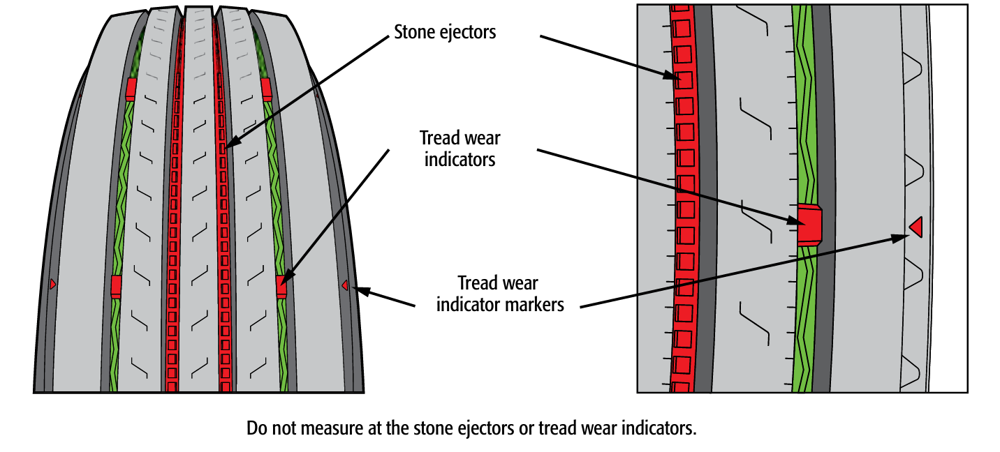
Inspect the tire tread to locate the area where the tread depth is lowest. Measure the tread depth at a any two adjacent major tread grooves, at three separate locations on the tire, using a suitable tread depth gauge. Do not measure tread depth on a wear bar. Tread depth measurements are to be recorded on an inspection report. The tread depth that is recorded must reflect the lowest tread depth measurement used to determine pass/fail condition.
Note: When any tire is replaced after a failed inspection, the tread depth of both the original (‘before’) and replacement (‘after’) tire(s) are to be recorded. Enter 'before' measurements in the "Measurements" section and 'after' measurements in the "Comments" section of the report.
A “major tread groove” is one of several of the deepest moulded grooves around a tire through the full thickness of tread rubber that include wear bars.
Item and method of inspection | Reject if | Inspection Class |
|---|---|---|
a) tread depth | a) on commercial vehicle with a gross vehicle weight rating of 5 500 kg or more, less than 3 mm of tread groove depth of a front tire or 1.5 mm of tread groove depth of a rear tire any tanker trailer involved with transportation of dangerous goods has less than 3 mm of tread groove depth on any tire on any other vehicle, less than 1.5 mm of tread groove depth on any tire Note: On a winter tire only, unless wear indicators are exposed, PASS WITH CAUTION if tread depth is more than 1.5 mm and less than 3.5 mm. Owners must be advised that tires do not meet minimum standards for use as winter tires (MVA 208, MVAR 7.162). tread worn to the extent that tread wear indicators in any 2 adjacent grooves of the tread contact the road surface | 1, 2, 3, 4, 5, 6 |
 | ||
d) tread condition | d) crack or cut, that is greater than 25 mm long, that extends deeper than a major tread groove crack or cut, extends into body cord, or any body cord is exposed any piece of original tire tread is and the longest dimension across the section is greater than 25 mm any flat spots or cupped to wear bars any section repairs done in a manner that does not meet any separation is evident Additional Inspection Procedure(s): Where possible, spin the wheel by hand and observe. | 1, 2, 3, 4, 5, 6 |
e) retread (re-capped or rebuilt tire) installation Note: An active steering axle is one that is directly controlled by the steering wheel. A passive steering axle responds to lateral force to turn wheels. | e) retreaded tire is installed on an active steering axle Note: Retreaded tires are permitted on a tag axle of a having either active or passive steering. Retreaded tires are permitted on vehicles inspected under inspection class 1, except business vehicles or commercial passenger vehicles (MVAR 10.19). | 1, 2, 3, 4, 5, 6 |
f) retread condition | f) retread material is , peeled, , or separated at the interface where the retread is bonded to the tire casing | 1, 2, 3, 4, 5, 6 |
g) regrooving | g) regrooving has been performed on a tire not marked “Regroovable” | 1, 2, 3, 4, 5, 6 |
h) studded tires | h) equipped with studded tires in violation of MVAR 7.1635 and 7.164 | 1, 2, 3, 4, 5, 6 |
i. any part of a belt, breaker strip or casing ply is visible in the tread area
ii. visible bump or bulge in the tread area indicating tread separation
iii. regrooved, recapped, or retreaded tire on front steering axle of any
iv. retread material is , , or separated at the interface where the retread is bonded to the tire casing and the longest dimension across the section is greater than 50% of the tread width
v. any piece of tire tread is and the longest dimension across the section is greater than 50 mm
vi. tire contacts any part of the vehicle
vii. tire regrooved and not marked “Regroovable”
viii. on commercial vehicle with a gross vehicle weight rating of 5 500 kg or more, less than 2 mm of tread groove depth of a front tire or 1 mm of tread groove depth of a rear tire
ix. on any vehicle (other than sub viii), less than 1 mm of tread groove depth on any tire
2. Tire Sidewall and Manufacturer Markings
Right Hand Drive Vehicles additional inspection requirements (see Appendix D).
Item and method of inspection | Reject if | Inspection Class |
|---|---|---|
a) matching and application Note: Nominal tire size is based on the size designation and marking provided by the tire . Tire diameter is determined by measuring the tire. | a) nominal tire size difference on an axle is greater than 25 mm dual-mounted tire diameters differ by more than 13 mm wheel/rim size does not match tire size required tire is radial tire is mixed with non-radial on an axle, or on a any tire is labelled “Not for Highway Use” or in any way that indicates the tire is not intended for on-road use directional tire incorrectly mounted | 1, 2, 3, 4, 5, 6 |
b) condition | b) ply separation is evident or body cords are exposed tire has a bump or bulge caused by tread or sidewall separation Note: A bulge of up to 9 mm in height, due to a sidewall repair, is acceptable. This bulge may sometimes be identified by a blue triangular label in the immediate vicinity. casing is broken or distorted presence of plug-type repair, or rubber coated or cured rubber plug is used in the sidewall dual tires making contact, or any tire making contact with any vehicle component UV degradation damage more than 3 mm deep | 1, 2, 3, 4, 5, 6 |
c) markings Note: Tires must have the letters “” or a “Maple Leaf” National Safety Mark embossed on the sidewall indicating that they meet Motor Vehicle Tire Safety Regulations. | c) sidewall markings do not meet the requirements outlined in CMVSS 109, 119, 139. | 1, 2, 3, 4, 5, 6 |
i. sidewall is cut or exposing the cord
ii. bias and radial tires are used on the same axle
iii. visible bump or bulge in the sidewall area greater than 9 mm in height
iv. dual tires make contact or any tire makes contact with any vehicle component
v. rubber coated or cured rubber plugs are used in the sidewall
vi. tire contact with any part of the vehicle
vii. any tire is labelled «Not for Highway Use» or in any way that indicates the tire is not intended for on-road use
3. Tire Inflation Pressure
Additional Inspection Procedure(s): Measure tire inflation pressure using a suitable gauge. Record pressure values on the inspection report.
Note: If a tire fails inspection due to over/under inflation condition, it is acceptable to add/remove air prior to completing the inspection. When inflation pressure is corrected, record found (before) and adjusted (after) pressure values on the inspection report.
Item and method of inspection | Reject if | Inspection Class |
|---|---|---|
a) inflation pressure Note: Recommended tire inflation pressure is based on data provided by the vehicle , or tire manufacturer relevant to tire application and load. | a) more than 10% above or below recommended pressure difference between dual-mounted tires is more than 10% leaking or inflation cannot be maintained within recommended pressure | 1, 2, 3, 4, 5, 6 |
b) valve stem | b) cracked, or inaccessible preventing gauging of pressure or re-inflation, or leaking valve stem cap is or | 1, 2, 3, 4, 5, 6 |
c) tire inflation system | c) is in a condition that any part of it could be hazardous to a person, or is in danger of falling off leaking air | 1, 2, 3, 4, 5, 6 |
i. any tire is inflated to 50% or less of the maximum inflation pressure marked on the sidewall
ii. tire is leaking
iii. tire inflation system is in a condition that any part of it is hazardous to a person, or is in danger of falling off
4. Wheel Hub
Item and method of inspection | Reject if | Inspection Class |
|---|---|---|
a) condition Note: Bearing fit in the hub is checked only when disassembled. | a) repaired by welding bent, broken, cracked, or distorted bearing cup is in hub bore | 1, 2, 3, 4, 5, 6 |
b) stud/bolt hole | b) any stud/bolt hole is enlarged or in a way that prevents proper fitting and retention of studs | 1, 2, 3, 4, 5, 6 |
c) wheel seal | c) of bearing lubricant from oil lubricated hub seal is allowing grease to be lost from hub seal is out of position | 1, 2, 3, 4, 5, 6 |
d) lubricant (oil lubricated) Note: Some hub/wheel-end assemblies use pre-set, unitized or extended service bearings, with sealed hubs. When contaminated lubricant is suspected, refer to the service literature provided by the . Confirm that a proper diagnosis is carried out before rejecting the vehicle, opening or disassembling this type of hub/wheel-end assembly. | d) lubricant level is below indicated minimum lubricant is contaminated with moisture or metal fragments of bearing lubricant from hub or hub cap | 1, 2, 3, 4, 5, 6 |
e) lubricant (grease lubricated) | e) grease is leaking from hub hub cap is cracked, or | 1, 2, 3, 4, 5, 6 |
i. any condition that exposes the internal components
ii. any evidence of overheating of the hub or lubricant
iii. lubricant not visible or measurable in hub
iv. wheel seal is leaking and contaminating the tire or the brake friction material or surface
5. Wheel Bearing
Additional Inspection Procedure(s): Check wheel bearing with axle raised sufficiently to rotate the wheel and hub assembly.
Rotate the wheel by hand through several full revolutions to check for bearing roughness or binding.
Check wheel bearing end-play/adjustment by pushing wheel assembly or hub inward and outward parallel to axle centreline.
Note: Checking in this manner may reveal movement in the hub and bearing that is additional to the bearing axial end play, e.g. a radial play between the bearings and spindle components may also be felt.
Confirm bearing axial end-play/adjustment on a non-sealed type hub with dial gauge if necessary. For pre-set, unitized or extended service bearings see additional note.
Some hub/wheel-end assemblies use pre-set, unitized or extended service bearings, with sealed hubs. When there is evidence of bearing damage, excessive wear, or excessive bearing end play, refer to the service literature provided by the . Confirm that a proper diagnosis is carried out before rejecting the vehicle, opening or disassembling this type of hub/wheel-end assembly.
Item and method of inspection | Reject if | Inspection Class |
|---|---|---|
a) axial end play/adjustment | a) does not meet the following criteria:
0.02 mm = 0.001 in., 0.13 mm = 0.005 in. | 1, 2, 3, 4, 5, 6 |
b) condition | b) binding or roughness is detected while rotating the bearing | 1, 2, 3, 4, 5, 6 |
c) locking device Additional Inspection Procedure(s): | c) bearing adjustment locking device is , not engaged or non-functional | 1, 2, 3, 4, 5, 6 |
d) damage Additional Inspection Procedure(s): | d) race or roller is or shows evidence of overheating | 1, 2, 3, 4, 5, 6 |
e) spindle or axle stub Additional Inspection Procedure(s): Must be inspected when the bearing is disassembled at the time of inspection. Note: Spindle or axle stub cracks or damage may involve non-destructive test / inspection to detect. | e) bearing fit onto spindle or axle stub does not meet or if there is no spindle or axle stub is cracked, or in a way that does not meet the or if there is no bearing condition or fit of the bearing onto the spindle prevents proper end play or adjustment from being maintained | 1, 2, 3, 4, 5, 6 |
i. axial end play is so excessive that imminent failure seems likely
ii. any evidence of overheating
iii. lubricant not visible or measurable in hub
iv. binding or roughness is detected while rotating the bearing
6. Wheel/Rim (Applies to all Wheel Types)
Item and method of inspection | Reject if | Inspection Class |
|---|---|---|
a) condition | a) wheel/rim is bent, broken, cracked, , distorted or modified wheel/rim has been welded or repaired in a way that is not in accordance with the Weld Repair of Aluminum Alloy Wheels Regulation homemade or remanufactured rim/wheel not stamped certified by Transport Canada or The Tire and Rim Association wheel/rim is or discoloured as a result of heating bolt/stud hole is elongated on a , any wheel has eccentricity or wobble in excess of 5 mm (3/16 in.) as measured at the rim | 1, 2, 3, 4, 5, 6 |
b) matching and size | b) wheel/rim size does not match tire size (diameter or width - i.e. tire stretching) on a , wheel/rim diameter is less than 250 mm | 1, 2, 3, 4, 5, 6 |
c) centre-lock knock off type | c) hub splines | 1, 2, 3, 4, 5, 6 |
i. wheel/rim, or any weld, is broken or cracked
ii. any welded repair on an aluminum wheel not in accordance with the Weld Repair of Aluminum Alloy Wheels Regulation
iii. wheel/rim has been welded or repaired in a way that does not meet
iv. on a , two or more wheel spokes broken or , or wheel cracked
7. Multi-Piece Wheel/Rim
Item and method of inspection | Reject if | Inspection Class |
|---|---|---|
a) condition | a) a component is bent, cracked, , distorted, improperly assembled or shifted out of position, severely corroded or pitted due to heating any component has been repaired by welding | 1, 2, 3, 4, 5 |
b) lock ring | b) there is less than 3 mm clearance between butt ends of the lock ring | 1, 2, 3, 4, 5 |
c) matching | c) mismatched wheel/rim component | 1, 2, 3, 4, 5 |
i. a lock ring is bent, broken, cracked, sprung, mismatched or improperly seated
ii. wheel/rim, or any weld, is broken or cracked
iii. wheel/rim has been welded or repaired in a way that does not meet
8. Spoke Wheel/Demountable Rim System
Item and method of inspection | Reject if | Inspection Class |
|---|---|---|
a) condition Additional Inspection Procedure(s): | a) there is damage in the 28° mounting area resulting from rim slippage, wear, corrosion or pitting there is evidence of rim slippage or incorrect positioning of rim on spokes lateral run-out exceeds 6 mm at sidewall of tire any welded repair on an aluminum wheel does not meet the Weld Repair of Aluminum Alloy Wheels Regulation | 2, 3, 4, 5 |
b) rim clamp | b) any rim clamp is broken, cracked, , repaired by welding, mismatched, twisted or worn out in the 28° mounting area any heelless clamp is bottomed or gap between clamp and spoke is more than 10 mm gap between clamp and spoke of a heel type clamp is more than 6 mm | 2, 3, 4, 5 |
c) spacer band | c) any spacer is collapsed, cracked, distorted, , the incorrect size or type, welded or repaired in a way that does not meet | 2, 3, 4, 5 |
i. wheel/rim, or any weld, is broken or cracked
ii. wheel/rim has been repaired in a way that does not meet
9. Disc Wheel System
Item and method of inspection | Reject if | Inspection Class |
|---|---|---|
a) installation | a) incompatible wheel or component is used on a wheel system wheel is incorrectly installed | 1, 2, 3, 4, 5, 6 |
b) condition | b) there is evidence of a or ineffective fastener there is evidence of damage or deterioration, foreign material, excessive or uncured paint on a hub, drum or wheel mounting face any welded repair on an aluminum wheel does not meet the Weld Repair of Aluminum Alloy Wheels Regulation | 1, 2, 3, 4, 5, 6 |
i. bolt/stud hole is elongated
ii. wheel/rim, or any weld, is broken or cracked
iii. wheel/rim has been repaired in a way that does not meet
10. Wheel Fasteners (Nuts, Bolts and Studs)
Additional Inspection Procedure(s): If the wheels are removed, wheel fasteners must be torqued.
Item and method of inspection | Reject if | Inspection Class |
|---|---|---|
a) installation | a) incorrect fastener type, thread direction or style is installed any nut is not fully engaged with the stud or bolt | 1, 2, 3, 4, 5, 6 |
b) condition | b) any fastener is bent, broken, or | 1, 2, 3, 4, 5, 6 |
c) fastener security Additional Inspection Procedure(s): Using a torque wrench set to the torque value specified by or , attempt to rotate each wheel nut to the set value. | c) any fastener rotates before reaching the torque specification set by or if there is no Note: A fastener that requires less than 1/6-turn to reach the specified torque value is considered slightly . A fastener that requires more than 1/6- turn to reach the specified torque value is considered very . Wheels must be disassembled for a full inspection when:
| 1, 2, 3, 4, 5, 6 |
i. wheel is
ii. any wheel nut or stud is broken, cracked, , , or threads are stripped